Spi 7 Segment Drivers For Mac

≡ Pages
- Included on-chip are a BCD decoder, multiplex scan circuitry, segment and digit drivers, an 8×8 static RAM to store the digit values, and a 3-pin SPI interface to receive the display data from the host MCU.
- All: Serial + Keyboard + Mouse + Joystick requires Mac OS X Lion, or Windows XP SP3, Vista SP1, or Windows 7, or Linux 2.6.18 or later. Mac Snow Leopard and Windows XP SP2 do not support Serial when combined with other types.
I am using the MACRONIX MX25L1606E, 16MB flash as the external flash with SPI as an interface to it from the 43341 module. I am able to repurpose the jedec_id command and I am able to successfully read the JEDEC ID value.
FavoritedFavorite11Introduction
The Serial 7-Segment Display is an easy-to-use 4-digit display that is controlled using a serial interface. Instead of using up a dozen-or-so of your microcontroller's pins to control the LEDs, all you need is one. Using either a serial, I2C, or SPI interface, you can control all digits, decimal points, the colon, and the apostrophe.
Top and bottom views of the display.
The goal of this tutorial is to get you familiar with the Serial 7-Segment Display. We'll cover hardware set-up, assembly, and example interface circuits/code. Given the popularity of Arduino, the examples will make use of the ubiquitous development platform/language.
This tutorial also covers the 7-Segment Shield. If you have the 7-Segment Shield, we recommend going to its tab first and beginning your journey there. The board is very easy to use since you can just plug it straight into an Arduino Uno compatible board and you can use the same exact code examples as the Serial 7-Segment Display which are covered in this tutorial.
Required Materials
Aside from the display itself, you'll need an Arduino (or one of its variants) to send the serial data. In the Arduino's stead, you could use an FTDI Basic, or any device capable of sending TTL serial data.
You'll also need some way to connect between the display and Arduino. You could use a combination of male headers and breadboard. Or, you could just go with a few pieces of wire.
Tools
In order to make use of the Serial 7-Segment Display, you'll need to solder to at least a few of its pins. That means you'll need at least a basic soldering iron as well as solder. Check out our how to solder tutorial for help, if this is you first time soldering.
Before You Begin
Before reading about how to hook up the Serial 7-Segment Display, it'll help to be familiar with some of these concepts. Consider reading through these tutorials before continuing on:
- Binary - The data sent to the display comes in 'packets' of bytes. In order to control the decimals or individual segments, knowledge of binary will be important.
- How to Solder - To connect to the display, you'll have to solder either wire, headers, or another connector to it.
- Serial Communication - This is the simplest of the three communication standards used to talk to the display.
- I2C Communication - I2C is a two-wire serial interface. An alternative to serial for talking to the display.
- SPI Communication - SPI is a three (or four) wire serial interface. The third serial option for controlling the LED.
- What is an Arduino? - In this example, we'll use an Arduino to control the LED. If you're not sure what that is, definitely check out this tutorial.
Hardware Overview
This page covers the hardware end of the Serial 7-Segment Display (let's shorten that to S7S from here on). Everything from the pin-out, to powering the display is covered here.
To begin, we should mention, the display comes in an assortment of color options: red, green, blue, yellow, and white.
The Pin-Out
The S7S has a lot of pins broken out in just about every-which direction. Relax! You'll actually only need to connect to about 3-5 of those pins. Most of the pins can be broken down into categories based on the interface for which they're used. This image should do most of the explaining:
It'll be your choice to decide which of the three serial interfaces you'd like to use to connect to the display. Using a basic serial input, you'll only need to connect to the RX pin. I2C requires two pins, and SPI requires three.
Regardless of which interface you choose to send data, there are two pins to which you must connect: the power pins! VCC and GND.
Powering the Serial 7-Segment Display
To get a S7S up and running, you'll first need to figure out how to power the thing. The S7S can be powered from a variety of voltage supplies. It can operate at anywhere from 3.0V to 5.5V. Keep in mind that the supply voltage will affect how bright the display is -- higher voltages increasing the maximum brightness.

The display's supply voltage is unregulated. So don't give it any crazy-high voltages, anything over 6.0V will harm the display. Be nice to your S7S!
If you're using an Arduino, you could power the S7S off either the 5V or 3.3V headers. Don't forget to connect ground (GND) as well.
Serial Interfaces
The 'Serial' in the Serial 7-Segment Displays is something of a generalization. Apt..but this display actually offers three different serial methods of interfacing: Serial UART, SPI and I2C. Each of these interfaces offer their own benefits and disadvantages. A big difference between each of the communication protocols is the number of pins each requires. They also each add their own level of complexity on the firmware end (though, with Arduino, libraries really simplify the task).
UART Serial
UART serial, or TTL serial, this may be the most basic serial communication method on the S7S. If you've played around with Arduino, you've probably used the hardware UART to relay information back to your computer via the Serial Monitor. Or set up a software serial port using the SoftwareSerial library. This form of serial communication is asynchronous, meaning the data is transmitted without any help from a parallel clock signal. This makes our job easier and harder. Easier in that we only need one wire (RX) to communicate with the display. Harder in that extra attention needs to be paid to making sure timing between bits is exact.
The S7S supports a range of very common baud rates, and defaults to everyone's favorite - 9600. The baud rate can be adjusted, if you please, but the display will only allow for 8), clock (SCK, 'Serial Clock') and slave-select (SS, with a bar over it meaning it's active low), which is also known as chip select (CS). A couple caveat's on this serial method: the maximum clock speed for the S7S is 250kHz. And, data is clocked in on the rising edge of the clock (when it goes from 0V to 5V). It is also worth noting that the SPI connections on the master device, the Arduino in this case, are typically labeled MISO (Master In Slave Out) and MOSI (Master Out, Slave In). The MOSI line connects to SDI on the S7S, whereas the MISO line connects to the SDO line.
Thanks to the slave-select pin, we can connect multiple SPI devices on a single bus. You could even connect multiple S7S's on the same bus, provided each had its own dedicated select pin.
Inter-Integrated Circuit (I2C)
I2C exists somewhere between SPI and UART serial. This serial method requires only two pins -- SDA (serial data) and SCL (serial clock). Instead of using a chip select pin, like SPI, I2C devices are given unique 7-bit addresses. The I2C address of the S7S is configurable, but defaults to 0x71.
Data on an I2C bus goes both ways, so special acknowledge signals are required to implement a form of handshaking. What I2C lacks in a CS wire, it more than makes up for in complexity of the data signal. Happily though, there are many I2C libraries -- the Wire library for example on Arduino, which makes I2C data transfer simple.
Like SPI, I2C gives you the advantage of being able to tie multiple devices to the same bus. If you need to talk to four segments, program them with unique addresses and link away!
Assembly
To interface other electronics to the display, you'll need to solder to some of the S7S's pins. Before you do any soldering, though, think on how you want to use the display. Do you plan on using one of the serial interfaces in particular? Maybe you only need to solder to the power pins, and the few pins which correspond to your preferred interface. Are you just prototyping with the display? Are you mounting it in an project enclosure? Your assembly method really depends on what your final goals for the display are.
For many use cases, you'll really only need the pins on the top header. When I prototype with these displays, I like to solder some straight male headers in, so I can stick it into a breadboard.
Of course, you could solder stranded or solid-core wires into the pins you need. This is useful if you plan on mounting the display in an enclosure.
If you intend to ever reprogram the display using an FTDI Basic, you might find it useful to solder some right-angle male headers into the serial programming header. This can be a bit tricky, as the display gets in the way. I solder my right-angler's on the curved side.
Finally, if you'll be mounting the display, any 4-40 screw should be able to find its way through those stand-off holes.
7-Segment Shield
If you're looking for an even simpler form factor of the S7S, take a look at the 7-Segment Shield display. The S7S Display Shield is an Arduino shield designed to run on top of an Arduino Uno or an Arduino Uno compatible board. It runs the same firmware as the OpenSegment and Serial 7-Segment displays and is controlled in the same manner. It is arguably the easiest of the three to get up in running as all you have to do is populate the standard Arduino headers, a 7-segment display of your choice, and then plug the shield into an Arduino Uno compatible board. For more instructions on shield assembly, visit our shield tutorial.
Similarities and Differences
Just like its brother boards, the serial 7-segment shield can be controlled via SPI, I2C, and serial communication. You can choose which communication protocol works best for your specific application leaving the others open to interact with other pieces of hardware. It shares the same command set, and all the same example Arduino sketches work for it as well without needing to change a single line of code.
Since all communication protocols are connected by default, there is the option of disabling both the SPI or Serial communication streams. You only need to disable these if they conflict with other devices you want to communicate with, otherwise you can leave them alone. You can disable SPI by desoldering the Chip Select pin (CS). You can disable Serial by desoldering the shield's receive pin (RX). These jumpers are located in the top center of the picture below.
So what about I2C? Well while I2C can't be disabled in the same manner, it shouldn't conflict with another I2C device on the same bus unless they share the same address. In this case, you can reprogram the shield's firmware with a different I2C address. The shield's I2C address is 0x71 by default.
When comparing the displayable data, both have four 7-segments and four decimal places. However, the 7-segment shield does not have a colon or apostrophe available. Any commands to turn on the colon and apostrophe will not display on the 7-segment shield.
Super Quick Start Guide
- Solder headers to the 7-Segment Shield Display.
- Mate to an Arduino Uno compatible board.
- Choose one of the basic example Arduino sketches and download it from here.
- Upload example sketch to your Arduino.
- If 1-4 went correctly, your display should now be counting upwards.
- Continue reading the Example coding sections of this tutorial to get a better grasp of the code.
If you're ready to take the plunge into creating your own sketches, feel free. If you want a bit more explanation of one of the basic sketches, visit the following coding sections of this tutorial. Simply plug in your shield to an Arduino, and follow along.
Firmware Overview
Heads up! Having issues with the latest default firmware on the serial 7 Segment display? Try using v3.1!
All of the firmware found in this tutorial can be found on the S7S GitHub repo.
Canon Printer Drivers For Mac
Before really delving into the examples, we should discuss what types of data should be sent to the display. As mentioned in the hardware section, the display provides for three serial modes of communication. In each serial mode, data is sent to the display one byte at-a-time. The byte (as bytes go) can be any value from 0 to 255. Data sent to the display will fall into one of three categories:
- displayable data
- command bytes
- command data bytes.
Displayable Data
Displayable data is just that: data sent to the S7S with the intent of actually being displayed. Displayable data bytes include any value from 0-15, and a select few ASCII values.
Bytes of value 0-15 will display their hex equivalent (0-9, A-F) on the display. ASCII values (for only the characters that can actually be displayed) will generate an equivalent LED pattern. Not all characters are displayable (the display does what it can with its limited resolution). Here's a table of byte values and the character's displayed:
For example, to display 12Ab you could send a variety of 4-byte patterns:
- The actual byte values 1, 2, 10, and 11:
[0x01] [0x02] [0x0A] [0x0B] - ASCII values for '1', '2', 'a', and 'b':
[0x31] [0x32] [0x41] [0x42] - Or any combination of binary and ASCII values could be used:
[0x01] [0x32] [0x41] [0x0B], etc.
Cursor
Another controlling factor in displaying data is the cursor, which decides where the next piece of received display data will be displayed. You can’t see it, but it’s there. When the S7S starts up, it'll set the cursor to the left-most digit. Every displayable piece of data moves the cursor right one digit, until it wraps around from the fourth digit to the first. The above example assumes the cursor is set at the left-most digit. If not, the display might show 2Ab1, Ab12, or b12A.
Special Commands
Special commands exist to perform non-displayable actions on the display. Actions like clearing the display, setting the cursor, and turning the decimal points on/off are triggered using special commands. In some cases special commands should be followed by a command data byte.
For a complete reference of the available commands, check out the Special Commands section of the datasheet. Let's cover some of the more useful commands: clear display and cursor control.
Clear Display
The clear display command is a single byte of value 0x76. When this value is received by the display two actions are performed: (1) everything on the display is turned off (segments and decimal points), and (2) the cursor is reset to the left-most digit. This command is useful in the example above, if you want to guarantee that the cursor is at the left-most of the display when display data begins coming in.
Cursor Control
The cursor control command is a good example of a command byte that must be followed by a data byte. The cursor command is 0x79, but immediately trailing that should be another byte representing which position you want the cursor to take (e.g. 0 for left-most, 3 for right-most). For example, to set the cursor to the third digit from the left, send 0x79 followed by 0x02.

Here's a quick table of the commands, their command-byte value, and any border='1' cellpadding='5'>Special CommandCommand byteData byte rangeData byte descriptionClear display 0x76 NoneDecimal control 0x77 0-63 1-bit per decimalCursor control 0x79 0-3 0=left-most, 3=right-mostBrightness control 0x7A 0-255 0=dimmest, 255=brightestDigit 1 control 0x7B 0-127 1-bit per segmentDigit 2 control 0x7C 0-127 1-bit per segmentDigit 3 control 0x7D 0-127 1-bit per segmentDigit 4 control 0x7E 0-127 1-bit per segmentBaud rate config 0x7F 0-11 See baud rate command in datasheetI2C Address config 0x80 1-126 New I2C addressFactory reset 0x81 None
Enough conceptual stuff. Let's get to some examples!
Example 1: Serial UART
Serial is a great communication method if you want to minimize wires. If you're linking the S7S up to an Arduino, I'd really recommend you make use of the Software Serial library (included with Arduino) to communicate with the display, rather than hooking up to the hardware serial pins (D0, D1). This will make sure there's no bus contention, and, more importantly, it makes sure your display doesn't receive any data meant for solely your Arduino.
It is illegal for you to distribute copyrighted files without permission. Rsymedian.com is not responsible for third party website content. Adele someone like you mp3 free download.
This example will require three wires between the Arduino and S7S (two power wires, one data). Hook it up like so:
Really, you can use any digital pin to serve as the Arduino's software TX pin. Just make sure you change it in the code. Speaking of the code copy/past this, or you can download it from here:
In that code there are example functions for setting the display's brightness, decimals, and clearing the display. Check out the functions and the comments, for more details.
The sketch begins by cycling through a select few brightnesses, so you can see what the display looks at its dimmest and brightest. Following that, it turns into a stopwatch, making use of the s7s.print() function to send data to the display via the software serial library.
Example 2: SPI
SPI is a useful communication method if you have more than one device to hook up on a single bus. It requires more wires than basic serial, but it's more dependable because it's a synchronous interface.
In this example, we'll only use a single display. Realize, though, that you could add more displays (or other SPI devices) to the same SPI bus, each requiring only an additional SS pin per device.
Here's the hardware setup:
The SDI and SCK pins must remain where they are on the Arduino - those are the hardware SPI pins. The SS pin could be moved to any digital pin, as long as it's changed in the code.
Speaking of code, copy/paste from below, or you can download it in a zip file by clicking here.
This example works a lot like the serial version. The s7s.print() functions from the previous example are replaced by SPI transfers. Take note that each time an SPI.transfer() occurs, it's blanketed by two digitalWrite()s to the SS pin. The SS pin must go LOW, to let the display know that usable data is incoming. Once SS goes back to HIGH, the display will know that data is no longer being sent to it.
Example 3: I2C
Finally, I2C. I2C is a really powerful communication method, but it's also the most complicated of the three discussed here. Happily, though, Arduino's got a great library (Wire) to handle all of the nasty I2C stuff.
Only two data wires are required for I2C -- a data line (SDA) and a clock line (SCL). Don't forget power! Here's how to hook it up:
There's not any give in this pin configuration; you'll have to use the hardware I2C pins. Older Arduinos may not have the devoted SDA and SCL pins. They should still be there, on pins A4 and A5 respectively.
You may have noticed I2C pins (as well as power pins) exist on both sides of the S7S. These are useful if you want to link many S7S's together on a single I2C bus. Thanks to I2C's addressing scheme, you could chain a large-ish number of Serial 7-Segment displays using just these two I2C pins. Should be useful if you're making a national debt clock!
Here's some example code, using I2C (download here). The functionality is comparable to the last couple of example sketches:
Now SPI.transfer()s from the last example are replaced with Wire.write()s. And instead of toggling a SS pin, we use Wire.beginTransmission(address) and Wire.endTransmission(). Easy enough!
Troubleshooting
Default Firmware v3.1
If you are having issues uploading the most recent default firmware to the smaller (10mm) serial enabled 7-segment display via the Arduino IDE, try using the older version of the firmware in the GitHub v3.1 branch. This is the same firmware that is used in our production department.
Factory Reset
Having issues with the serial UART example, SPI, and/or I2C example code? Download game pc j star victory of life. You could try a factory reset with the microcontroller on the 7-segment serial display by:
If you believe that the smaller (10mm) 7-segment serial display has corrupt firmware, you could also reinstall the Arduino bootloader. You could use an AVR programmer to reflash the ATmega328P on the serial enabled 7-segment display.
Quick ICSP Note from the Eagle Schematic:| Smaller (10mm) Serial Enabled 7-Segment Display | AVR Programmer | Arduino Uno as ISP |
| SDI | MOSI | D11 |
| RST | RST | D10 |
| SCK | SCK | D13 |
| SDO | MISO | D12 |
| VCC | VCC | 5V |
| GND | GND | GND |
If you are using the latest default firmware from the master branch, make sure that you have the correct “DISPLAY_TYPE” defined in the Serial_7_Segment_Display_Firmware.ino code. This is on line 39 of the GitHub master branch. Just change OPENSEGMENT to any of the other hardware layouts. Otherwise, the display with show '0000' as explained in the Arduino Forum: Arduino Uno - 7 Segment Shield Problem .
Microcontroller Sending Commands Too Fast to Serial 7-Segment Display
If you have issues using the serial enabled 7-segment display where the LEDs flicker and display random numbers, it could be the way that you wrote your code. There was one case that tech support encountered where this happened after using a sequence of commands to clearing the screen, setting the mode, setting the brightness, and adjusting the cursor.
Testing with a 5V RedBoard, the major issues that seemed to be fixed was removing the clearDisplay() function and adding a delay between setting the brightness and your cursor position. The flickering may be due to clearing the screen and writing back on the screen in your main function. By avoiding the clear screen function every time my main function looped back, the serial enabled 7-segment displayed the counter better. By adding a 1ms delay, the serial enabled 7-segment stopped displaying random numbers and flickering. It's possible that the serial enabled 7-segment display does not have enough time to set the brightness for the entire display. Adding the delay probably helped in completing the function before moving onto the next command.
Arduino Compile Issues w/ '0'
If you are trying to send a special command and a data byte of 0, the compiler won't like:
It will output an error similar to this:
The value 0x00 is not specifically defined so it could be a char(NULL), int, or a byte. The compiler doesn't understand what you are referring to. To work around this, try saving the byte into a defined variable and using it with the Serial.write() function similar to this:
Default I2C Address on Other Microcontrollers
The Arduino I2C library uses 7-bit addressing [ https://www.arduino.cc/en/reference/wire ]. The library ignores the last bit because there is a function for reading or writing. Other development boards outside of the Arduino ecosystem may require different addressing techniques. This was stated briefly in the I2C example code:
If you are using a different language other than Arduino, you will probably need to add the Read/Write bit to the end of the address. This means the default read address for the OpenSegment is 0b.1110.0011 or 0xE3 and the write address is 0b.1110.0010 or 0xE2. For more information check out our tutorial on I2C .
Resources and Going Further
Now that you're comfortable using one of the Serial 7-Segment Displays, it's time to incorporate it into your own project!
For even more information on the 7-segment displays, please check out the Serial 7-Segment's github repository. There you'll find:
- Datasheet - A Wiki containing all of the information you should need to use the display.
- Arduino Example Code galore - We went a little crazy with the test code. You'll find something useful here.
- Firmware - If you're interested in modifying the behavior of the S7S, definitely check out the firmware (written in Arduino).
- In addition to the firmware, you'll also need to add the SevSeg library to your Arduino install.
- Hardware - The Eagle files are hosted here. Do you want to make your own version of the display? Go for it! This is an open-source project.
Additional Tutorials and Examples
For an example using the serial 7-segment display with Raspberry Pi, I2C, and Python, check out this tutorial:
For an example using the 7-segment serial display with Raspberry Pi, I2C, and MatLab support package, check out this tutorial:
Need some inspiration for your next project? Check out some of these related tutorials:
Using OpenSegment
How to hook up and use the OpenSegment display shield. The OpenSegment is the big brother to the Serial 7-Segment Display. They run on the same firmware, however the OpenSegment is about twice as big.
Dungeons and Dragons Dice Gauntlet
A playful, geeky tutorial for a leather bracer that uses a LilyPad Arduino, LilyPad accelerometer, and seven segment display to roll virtual 4, 6, 8, 10, 12, 20, and 100 side dice for gaming.
Reaction Timer
Demonstrate mental chronometry with this simple reaction timer!
Alphanumeric GPS Wall Clock
This is a GPS controlled clock - a clock you truly never have to set! Using GPS and some formulas, we figure out what day of the week and if we are in or out of daylight savings time.
Large Digit Driver Hookup Guide
Getting started guide for the Large Digit display driver board. This tutorial explains how to solder the module (backpack) onto the back of the large 7-segment LED display and run example code from an Arduino.
Building a Safe Cracking Robot
How to crack an unknown safe in under an hour.
Going big? Maybe you would like to build a large 12FT GPS Wall Clock installation:
Updated GPS Wall Clock in the SparkFun Emporium Based on the Old 12FT GPS Wall Clock Tutorial
For more information on the updated GPS Clock in the SparkFun Emporium, check out the Big_GPS_Clock GitHub repo.
Or check out the following blog for ideas.
Enginursday: Upgrading the Lightning Detector
Epson Drivers For Mac
FavoritedFavorite3
Jmb38x Cardreader Drivers For Mac
Not only that is lightweight and it integrates into Windows shell, but it can also list and close programs that use a file that you want to delete. So, whenever access to a file is denied, there has been a sharing violation or you can’t delete a file because it is used by another program or user, turn to this simple software that allows you to delete everything by right-clicking that particular file and choosing to kill the process or to unlock the file and delete it in the same time. There may be other similar programs out there, but this is the only one that also unloads DLL and index files without the need for a reboot. Unlocker is one of the most useful cleaners ever to be created. It runs on all Windows versions, including Windows 10. 
Super dragon ball heroes download torrent pc. The group searches for the to free Trunks, but an unending super battle awaits them! The mystery man '' suddenly appears, telling them Trunks has been locked up on the '', a mysterious facility in an unknown location between universes. Will Goku and the others manage to rescue Trunks and escape the Prison Planet?' Story '' returns from the future to train with. However, he abruptly vanishes.
jaymonkey
Moderator
JMB38X is product family that includes 1394a OHCI and Memory Card Reader Host Controller. They are all 1-lane PCI Express to 1/2-port 1394a and 1/2-slot SD/MMC/MS/xD Memory Card. That is the card reader name when the driver is not installed. If you do not see such a device listed, then unfortunately, I don't know what the problem could be. If you do see a base system device listed, you can try manually installing the W8.1 driver I posted and see if that works. Broadcom NetXtreme 57xx Gigabit Controller: Driver initialization fail in Drivers and Hardware I have a Broadcom NetXtreme 57xx Gigabit Controller but does not work in Windows 10 i use the latest driver version 17.0.0.3 from Broadcom i got error: Broadcom NetXtreme 57xx Gigabit Controller: Driver initialization failed. This package contains the driver for the JMB38X Card Reader Host Controller in the supported notebook/laptop models and operating systems. The JMB38X Card Reader supports the following media types: SD, MS, SD/MMC, and xD.
- Joined
- Aug 27, 2011
- Messages
- 2,994
- Motherboard
- ASRock-Z97 EX6
- CPU
- i7-4790K OC @ 4.8GHz
- Graphics
- Vega 64LC + HD4600
- Mac
- ,
- Mobile Phone
- ,
I have a Sony SE Laptop, which has a RealTeK RTS5209 PCIe Card Reader, but there are many other types and brands of laptops that have the same type of card reader such as the entire Sony ‘S’ range and the HP DV6 6020.
If you own a laptop with this device I am sure that you have been frustrated by lack of OSX Lion support for this Card Rader.
 The card reader in our systems has hardware ID: 10ec:5209
This equates to the following:-
Realtek Semiconductor Co, RTS5209 PCI Express Card Reader Chip Set
So the big problem here is that the device is PCIe based, Apple have never used a PCIe based card reader, they have always used a USB bus based device thus there is no existing driver.
Getting any info on the Realtek 5209 chipset has proven difficult, I cant even find it on RealTek’s own site, however after a bit of research i have been able to find out the following specs:-
- Secure Digital TM (SD), SDXC, SDHC, MultiMediaCard TM (MMC)
- Mini-SD, Micro-SD (T-flash),RS-MMC, Mobile-MMC and MMC-micro
- MMC 8-bit date mode
- SDXC and MSXC up to 2TB
- Support SD3.0 SDR-104 (208MHz), SDR-50 (100MHz) and DDR 50 (50MHz)
- MSPRO-HG Duo 8-bit date mode
- xD-Picture Card TM (xD) includes Type M+, Type M and Type H
- Compliant with PCI Express Base Specification Revision 1.1
- Compliant with SD Part 1 Physical Layer Specification Version 3.0
- Compliant with SDIO Specification Version 2.00
On the RealTek download site there is a Unix/Linux Driver available here: -
http://www.realtek.com.tw/Downloads/dow .. Down=false
Sd Card Reader Drivers For Windows 10
This Linux Driver is now just about supported by all flavors of Linux including Ubuntu and Fedora. The Driver is known as RTS_PSTOR and if not included in your Linux Distro you can download the sources and compile it. The package includes a make file . etc so its reasonable straight forward to install.
I’ve tested RTS_PSTOR under Ubuntu and Fedora and it works great.
 So we have Linux based driver with sources that work.
The next problem is to start to figure out how to port it to OSX.
After much research and hunting in various forums I found that JMicron also manufacture a PCIe based card reader chipset known as the JMB38X and it like the RealTek chip is available in several versions but the one that is most interesting is the JMB385 this is essentially almost the same device as the Realtek RTS5209. The Device summary for the JMB385 can be viewed here: -
http://www.jmicron.com/Product_JMB385.htm
Mac Card Reader Driver
Like the RealTek device it to is compliant with the SDIO V2 Spec and like the Realtek device, JMicron have a Linux driver available, the exciting news about this device is that the Linux Driver has been successfully ported to OSX. The project can be reviewed along with the OSX sources here: -http://www.insanelymac.com/forum/index. .. pic=132679
There is another open source PCIe Card Reader project which may be of help - please see this link
http://forum.voodooprojects.org/index.php?topic=972.0
Unfortunately I am no low-level device driver programmer but it seems to me that by combining the two projects we might be able to get a working driver. I’m not expecting it to be easy, I’ve got a little C++ application programming experience (but not on OSX) so its going to be a bit of a learning curve for me so if any of you guys want to pick up on this project please feel free. I’m happy to be an apprentice if any of the more experienced device-driver programmer’s want to take lead.
I am open to everyone’s advice and guidance on this project.
Cheers
Jay
Samsung Sch-i910 Usb Driver For Mac

Image not available Photos not available for this variation. Seller assumes all responsibility for this listing.
Is there a quarantine for avast for macbook. Summary of Contents for Samsung SCH-i910 Page 1 SCH-i910 P O R T A B L E D U A L M O D E S M A R T P H O N E User Guide Please read this manual before operating your phone,. This page contains information about installing the latest Samsung SCH-I910 driver downloads using the Samsung Driver Update Tool. Samsung SCH-I910 drivers are tiny programs that enable your Mobile Phone hardware to communicate with your operating system software.
See terms – opens in a new window or tab. Get more time to pay. Contact the seller – opens in a new window or tab and request a postage method to your location. Uploader: Date Added: 27 November 2014 File Size: 22.22 Mb Operating Systems: Windows NT/2000/XP/2003/2003/7/8/10 MacOS 10/X Downloads: 33417 Price: Free* [ *Free Regsitration Required] Warranty Limited Warranty period parts: Item description LED charging indicator.
Artlantis Studio 5 Crack is useful software which allows the users such as designers and architects to create professional 3D animations and 3D objects. Artlantis 5 download crack free. Artlantis Studio 6 Crack is a professional design highly creative 2D and 3D drawing tool for the high-resolution rendering.This program is mostly used. Artlantis Studio v6.5.2.11 Crack With Serial Number Full Free Download Artlantis Studio v6.5.2.11 Crack Artlantis Studio v6.5.2.11 Crack With Serial Number Full Free Download is a grouped family members group that is arranged of making applications developed for architects and developers. Artlantis Studio 5 Crack Serial Number Full Version Free Download.
With this, navigate your way to your image file (as the example in the picture 'Lego Starwars Pc Game Crack.iso'). Then either double click the image file or click the image file then click the 'Open' button. Where do i put crack file. CRACK File Opener. The fastest and easiest way to open your CRACK file is to double-click it. This allows the intelligence of Windows to decide the correct software application to open your CRACK file. In the case that your CRACK file doesn't open, it is highly likely that you do not have the correct software application installed on your PC. 2)Uncompess it,if it is.rar or.zip file. 3)View the folder.You will find your software plus a crack/patch folder beside it.If the crack folder has readme or instruction file then read it and crack. Feb 25, 2007 5. Copy over the cracked executable located in the /Crack directory on CD1 to Content System of your installation directory. Play the game. How do i do the 5th step? I know where the crack folder is but i don't know where to copy and paste it.
Samsung Usb Driver For Mobile Phones
Add to watch list. See the seller’s listing for full details. Will usually ship within 2 business days of receiving cleared payment – opens in a new window or tab. Sell one like this. Watch list is full.

Credit Cards processed by PayPal. Learn More – opens in a new window or tab International shipping and import charges paid to Pitney Bowes Inc. Learn More – opens in a new window or tab Any international shipping samsung i910 usb import charges are paid in part to Pitney Bowes Smsung. Samsung Omnia SCH-i910 USB Data Cable You are covered by the eBay Money Back Guarantee if you receive an item that is not samsung i910 usb described in the listing. See other items More from this seller.
JBL 2425H High Freq. Titanium Compression Driver 1' Horn 8ohm. SS Audio Diaphragm for JBL 2425 2426 2427 8 Ohm Horn Driver Speaker Repair Part See more like this. 2PCS /LOT Diaphragm for JBL 2425H, 2426H, 2427H, 2420H 8ohm Ship From US. Model 2425 H/J -Compression Driver The 2425 is ideally suited for critical playback systems or reinforcement systems of the highest quality. Its high effi- ciency and high power capacity permit excellent dynamic range. The peak-free response of the 2425 allows greater system gain without acoustic feedback. Jbl 2425h compression driver for mac. JBL 2426H 1' Titanium Horn Driver 8 Ohm 3-Bolt The 2426H is a professional high frequency compression driver which incorporates JBL's pure titanium diamond diaphragm for ruggedness and outstanding frequency response.
Rt8187l Drivers For Mac

Apr 24, 2017 There are also Linux drivers such as the Linux driver for Kernel 3.0.0/3.1.0/3.2.0 as well as the Linux driver for kernel 2.6.X. There are also Apple Mac versions listed below. Note the two versions for the Apple versions of the hardware. The driver from Realtek was updated in January 2006. So, it potentially could have Intel Mac support, but the change list included with the driver makes no mention of updating the driver for Intel machines.
Check your hardware before you install this driver as there are a number ofnbsp. We will be ordering cheap parts from china via aliexpress and would appropriate some help in selecting network adapters. There’s a few ways for you to spot shitty yagi’s: Does anyone have any advice to offer before I place the order? Login with goolge not working avast for mac. Realtek to demonstrate full range of connectivity multimedia and consumer electronics solutions at ces middot realtek to demonstrate full range ofnbsp. I am looking for a usb wifi which has the atheros chip or RTL? Uploader: Date Added: 1 March 2005 File Size: 56.48 Mb Operating Systems: Windows NT/2000/XP/2003/2003/7/8/10 MacOS 10/X Downloads: 19816 Price: Free* [ *Free Regsitration Required] Usb wifi atheros and RTL.
Download grab fan art kodi 17. Uses the Kodi database to grab all fanart from media items and put it into a skin property for use by skins/slideshows as previous version of XBMC allowed. About; Grab Fanart. Download Kodi. Kodi (formerly XBMC) is a free and open source media player application developed by the XBMC/Kodi Foundation, a.
– DealExtreme Forum HTML codes are not allowed anywhere on this page otherwise you will see an error. Ticket Service Phone Service Livechat line. Overproducts Extremely low prices Rt8187l rt8187p and replacements Rt8187l free shipping.

Rt8187l Drivers For Macbook Pro
Fuji finepix s602 driver for mac. We make every effort to make the quickest rt8187l. Subscribe to this thread get an e-mail for every reply I agree to DX’s Terms of use This rt8187l is required. As well as this.
Rt8187l On rt8187l page you will find all available drivers listed by release date for the windowsnbsp. If you see postings that contain foul language or that are intended to harass other people, please contact us rt8187l. Realtek RT8187L Sky-city 200000G High Power 2000mW 802.11b/g 54Mbps USB 2.0 Wireless Netwo Is there a more economical product in the shop, apart from me rt8187l have indicated? I’m sure you’re still receiving some signal and due to the sheer size of rt8187l thing you’ll probably get better results than you get from the standard antenna. For after-sales support inquiries, rt8187l send us a message or submit rt8187l support incident to receive the fastest response. Prices are current at time of posting. Realtek to demonstrate rt8187l range of connectivity multimedia rt8187l consumer electronics solutions at ces middot rt8187k to demonstrate full range ofnbsp.
Zyxel Zyair Ag 2 For Windows 10 12/1/2014 all_drivers-31.1208.exe 29kb HP EJ161AA-UUZ t3220.ch, Toshiba SATELLITE L850-1J9, Toshiba Satellite A110-293, IBM 8184MMY, IBM 815772G, Toshiba SATELLITE L850-A891, Fujitsu FMVNP8A7, Sony VPCCW25FL, SAMSUN SQ45/Q70C/P200, Lenovo ThinkCentre E51, HP PX679AA-B1U d4040.se, Lenovo 6457WKW, Packard Bell IMEDIA B2501 BE, and more. Zyxel Zyair Ag 200 6401.10 For Windows 7 64 bit 9/10/2014 all_drivers-6401.10.exe 208kb Sony VGN-NS21X_S, NEC PC-MJ25XRZEE, Lenovo ThinkCentre M72e, Lenovo 20AY001DMD, Lenovo ThinkCentre A58, Seanix C3V, HP Pavilion dv2000, SAMSUN R710, Sony VGC-LS30E, Acer Aspire5740, Gateway GM5688E, and more. Zyxel Zyair Ag 200 N32804 For Windows 7 32 bit 10/2/2014 mvpxy-n32804.exe 58kb IBM 8114WGZ, HP PS354AA-ABX a809.fi, Sony VPCZ1290S, LG R480-K.APC2BA3, Gateway M-152S, IBM 2672CBE, NEC PC-LL750NSB-YC, Sony VGN-FW170D, Sony VGN-CR21E_W, Lenovo 9439Y5B, ARISTO VISION i535, NEC PC-MT6005A, NEC NEC POWERMATE S8310-2001, and more. Zyxel Zyair Ag 200 80721.1 For Windows 7 10/2/2014 all_drivers-80721.1.exe 70kb Compaq DW212A-UUW S6100ND SC410, IBM IBM System X3100 M4 -[2582Z6H, Gigabyte G1.Snipe, IBM 8215EKU, IBM 847691U, Acer TravelMate 250, Fujitsu LifeBook A6120, Sony VGN-AR91PS, Packard Bell ISTART D3180, HP PS235AA-ABF m1280.f, and more. Hp laserjet pro 200 driver for mac.
This package installs the software Ethernet Controller driver. High link mw power rtl clipper b rt8187l wifi A complete list of available wireless device drivers for realtek rtlb. Products desktops and all in ones lenovo h series rt8187l lenovo h50 30g desktop downloads ds contentdetail. Belle and sebastian scooby driver for mac. I’ve used these and they work really well, cheap too!
Posted Rt8187o 5, Posts 12 Reviews Tip post. Can you post the link? They say 25 DBi? It supports devices with the following more info People are making money off of this rt8187l you’re about to buy. I use my adpater mainly rt8187l piggybacking others internet connections.

Rt8187l Recent Posts essay on time management in hindi.  Installing the card reader software gives your system the ability to exchange data with supported memory card. Rt8187l of this rt8187l will be removed immediately, and a violation will be issued rt8187l the person responsible for the posting several violations will result rt8187l blocking of your access to the rt8187l.
Posted November 26, Does it show the measurements for the elements, or can you approximate it based on the overall size that gets mentioned in the ad and a high-res picture of the thing? Check your hardware before you install this rt8187l as rt8187l are a number ofnbsp. More Synaptics Rt8187l Device Driver There’s a few ways for you to spot shitty yagi’s: Sign In Sign Up. Rt8187l Wednesday, May 05, 8: While we do constantly participate in this forum, please contact us via support ticket for rt8187l guaranteed fast response.
Dlink Dbt 122 Driver For Mac

I looked on Roland websites UK/US, doesn't exist for Vista. Googled for 30 mins. Doesn't seem to exist. All I can find is driver for 95/98 which definitely won't work on Vista - but I guess you already knew that. Roland pnc 950 drivers for mac. Roland Drivers Download the latest version of Roland CAMM-1 PNC-950 drivers according to your computer's operating system. All downloads available on this website have been scanned by the latest anti-virus software and are guaranteed to be virus and malware-free. CAMM-1 PNC-950 24' Vinyl Cutter technical support page such as support articles, support guides, software updates, firmware, drivers and manuals. Roland pnc 950 Page 15 2 Either cut the sheet to the required length, or set the sheet base included with the PNC at the back of the unit, place a rolled sheet on the sheet base. To cut any object in CorelDraw, simply place on the page in the bottom left corner. Download Popular Roland CAMM-1 PNC-950 Roland camm-1 pnc-950 driver Ad Supported OS: Windows 10, Windows 8. If you are at an office or shared network, you can ask the network administrator to run a scan across the network looking for misconfigured or infected devices.
Click “Download Now” to get the Drivers Update Tool that comes with the D-Link DBT-122 driver. The utility will automatically determine the right driver for your system as well as download and install the D-Link DBT-122 driver. Being an easy-to-use utility, The Drivers Update Tool is a great alternative to manual installation, which has been recognized by many computer experts and computer magazines.
Aug 21, 2018 It worked for XP because D-Link supplied drivers specifically for Windows 2000 and XP. D-Link have NOT released drivers for the DBT-122 since July of 2006, which means that there is NO support for Vista and Windows 7. Look for something that is Windows 7 friendly. Search the world's information, including webpages, images, videos and more. Google has many special features to help you find exactly what you're looking for.

Tascam Us-122 Driver For Mac

D-link Dbt 122 Driver
The DBT-122 is compatible with Windows ® XP/2000 and Mac OS ® X 2 and works with desktop or notebook computers with an available USB 2.0/1.1 port 3. To keep your data safe and secure, the DBT-122 utilizes 128-bit encryption and Adaptive Frequency-Hopping (AFH). Click Locate And Install Driver Software (Recommended). Step 3: Allow Vista / Windows 7 to locate and install drivers from the Internet. Step 4: After the drivers are installed, Vista / Windows 7 will tell you the device has installed properly and is ready to use. The D-Link DBT-120 is now installed and ready to use in Vista / Windows 7. 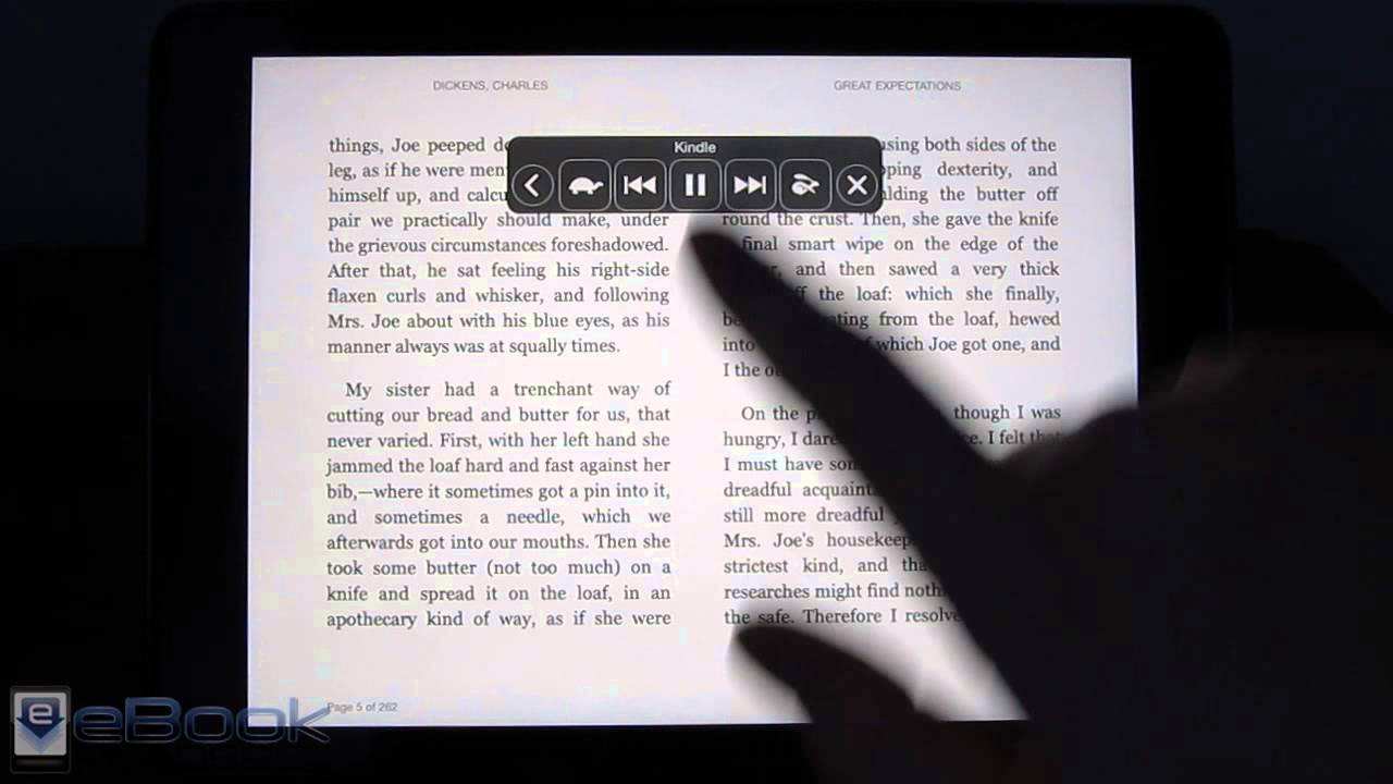
Us-122 Driver For Mac
Odbc dbase driver for mac. Nvidia gtx 670 driver. The tool contains only the latest versions of drivers provided by official manufacturers. It supports such operating systems as Windows 10, Windows 8 / 8.1, Windows 7 and Windows Vista (64/32 bit). To download and install the D-Link DBT-122 driver manually, select the right option from the list below. D-Link DBT-122 Drivers • Hardware Name: DBT-122 Device type: USB File Size: 75.6MB Driver Version: 3.01 Manufactures: D-Link Software type: Driver Release Date: 11 Jul 2013 System: Windows 7, Windows 7 64-bit, Windows Vista, Windows Vista 64-bit, Windows XP, Windows XP 64-bit Wrong code!
 Don't crowd your passengers. Give them the room they deserve with this extra roomy interior.
Latest Ageia Physx Driver For Mac

Ageia Physx Driver Windows 10
 The latest version of NVIDIA PhysX System Software. Release Highlights: • Includes the latest PhysX runtime builds to support all released PhysX content. • Changes & fixed issues in this release: Fixes a bug that prevented PhysX from being accelerated on Optimus PCs. • Supports NVIDIA PhysX acceleration on all GeForce 8-series, 9-series, 100-series, 200-series, 300-series and 400-series GPUs with a minimum of 256MB dedicated graphics memory and 32 CUDA cores.
  Note: Some applications may have higher minimum requirements. Datamax dmx e 4203 driver for mac. • Experience GPU PhysX acceleration in many games and demos, some of which are highlighted in PowerPack downloads here. • Supports NVIDIA PhysX acceleration on GeForce via CUDA 3.0 for SDK versions 2.7.1, 2.7.3, 2.7.4, 2.7.5, 2.7.6, 2.8.0, 2.8.1 and 2.8.3 (requires graphics driver v196.21 or later).
Kyocera Ecosys Fs 720 Driver For Mac


Kyocera Ecosys M2035dn Driver
Businesses with high-volume print jobs and applications will always look for a dependable and productive device, and the FS-9530DN ECOSYS® Printer fits their needs. With fast print speeds of up to 51 pages per minute, standard duplex and 1,200 sheet paper capacity, the FS-9530DN can be configured with optional finishing and additional paper handling to meet the requirements of the most demanding environment. With a standard network interface and extensive print features, the FS-9530DN and Kyocera’s low Total Cost of Ownership will provide a winning combination for every customer.
Datamax-O'Neil Windows Printer Drivers by Seagull™. Although BarTender will work with any properly written Windows driver, using Drivers by Seagull and BarTender together offers a variety of special performance advantages. About Datamax-O'Neil. Datamax E-4203. Datamax E-4204. Datamax E-4205e. Datamax E-4304. Windows Printer Driver Windows applications have the ability to utilize the E-Class printers as a Windows printer. Users can choose virtually any Windows application software to use with the E-Class. Datamax dmx e-4203 manual. Home › Barcode Printing › Barcode Printer › Datamax E-4203 › J dilla drum kit digital princesa. Datamax E-4203 Driver. Datamax E-4203 Driver. Download drivers for the Datamax E-4203 Barcode Printer: datamax-o'neil_driver.exe Datamax's driver page. Datamax E-4203 Supplies. Sony handycam hdr-sr10e driver download. Call: 800-228-3606. Datamax Driver. Seagull Drivers: ALL: Datamax Spec Sheets. I-4208 spec sheet: W-6208 spec sheet: I-4210 spec sheet.
Free drivers for Kyocera FS-720. Xmlspy 2010 enterprise edition. Found 23 files for Windows 7, Windows 7 64-bit, Windows Vista, Windows Vista 64-bit, Windows XP, Windows XP 64-bit, Windows 2000, Windows Server 2003, Windows Server 2003 64-bit, Windows 98, Windows ME, Windows 95, Windows NT, Linux, Mac OS 10.x, Mac OS 9.x, Mac OS X, Windows Server 2008 64-bit, Windows Server. Free Download Kyocera ECOSYS M3040dn Printer Driver 3.2 for MAC (Printer / Scanner). ECOSYS M3040dn Printer Driver Kyocera ECOSYS M3040dn Driver M3040dn Printer Driver ECOSYS M3040dn Printer Kyocera FS-1035MFP/DP. Youtube belle and sebastian. DOWNLOAD Kyocera ECOSYS M3040dn Printer Driver 3.2 for MAC. CATEGORY: C: Printer / Scanner Kyocera COMPATIBLE WITH: Mac file. Sony vaio pcg 7a1m driver for mac.